Brüel Acoustics
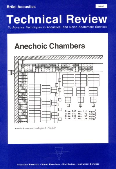
Anechoic Chambers
By Dr. techn. Per V. Brüel
Noise standards for many products ranking from household equipment, tools and ventilators to cars and buses require anechoic rooms for accurate testing. Also in development work anechoic chambers are a must for serious work with abatement of noise. The most easy way to make frequency and directional characteristics of loudspeaker systems is in an anechoic chamber. As noise standards will have an increasing importance for manufacturing and selling of industrial products containing moving parts, a large number of anechoic chambers must be produced.
In the future we will see an increasing number of noise standards which require three types of rooms:
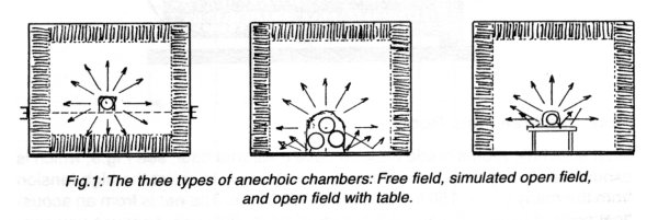
1) Free field where no reflections from any items and inner surface of the measuring place can be tolerated, and
2) Simulated open field where the bottom plane in the measuring room is sound reflecting. That means the floor in the room must be made of concrete, very hard wood or tiles. In Fig.1 different rooms are shown.
3) Simulated open field with a standard table for testing household equipment, computers, tools and other items used on a table.
Free Field Room
This room is used for testing microphones, telephones, hearing aids, sound level meters, and other small products. In most cases a relative small room will be adequate as the objects are small. Free field rooms will in some institutions be used for psycho- acoustic research, but here a bigger room is necessary and the sound insulation is also essential which makes this type of testroom very expensive.
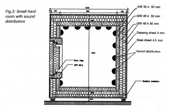
It is often seen that an anechoic chamber intended for measuring on industrial products is built on floating concrete and with heavy sound insulation. This is an expensive solution of little use, as practical all products can be tested at high levels as most elements in the measuring chain are linear. An exception is testing of very low noise level for example a disc drive to a computer or a watch. But such low noise level objects should be tested and controlled in a little hard room with very high sound insulation for both room and door, see Fig.2. A small box like that is much cheaper than an anechoic test room and much faster to work with. The test box can be used on a production line checking the noise of the product.
Floor in a Free Field Room
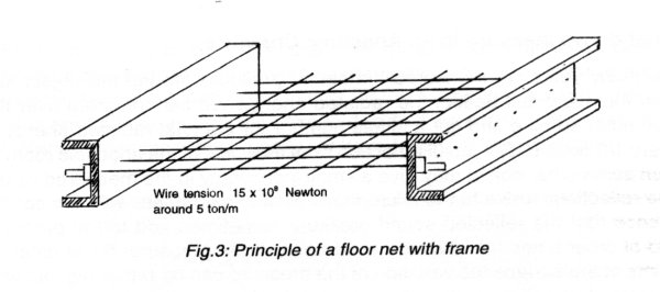
Most anechoic rooms made hitherto have a wirenet floor, see Fig.3, which is expensive. A very heavy metal frame is necessary to resist the high tension from the many wires, 150 kg/3cm which is 5 ton/m. The net is from an acoustical point of view excellent, but not practical in daily use, because you can- not walk on the net without shaking the object and the measuring instrument. If you happen to drop a microphone cartridge, pencil or watch, it is complicated to get it back.
Therefore it is a good idea in a free field room to have some hooks in the ceiling to support the objects and a rotating beam for the microphone.
Simulated Open Field
As more and more regulations and standards require a reflecting floor it should be worthwhile to consider to build only a semi-anechoic room. For the time being we estimate that only 25% of all measurements require a free field room and future trend is going to use more rooms with reflecting floor. Because it is more in line with daily use of the object, it is cheaper to build and require less room in the building, see Fig.1. Large products like cars, buses, motor cycles, tool machinery, washing machines, refrigerators, and all other equipment intended for staying on a floor or on the ground should be measured in a semi-anechoic room.
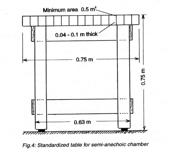
Smaller household equipment e.g. coffee machines, mixers, sewing ma- chines etc., and all other products intended to stand on a table should be placed on a table in a semi-anechoic chamber, see Fig.4.
What do we measure in an Anechoic Chamber
For many years we measured the sound pressure around the object and from this we could deduct the radiated energy. We can integrate over the total outer surface and get a single number for the total radiated energy in every 1/3 octave. The small reflection from the walls of the anechoic room or from some other object may give a small inaccuracy in the measured value. The reflections arrive to the microphone in different phases with the consequence that the reflected sound pressure sometimes add to the pressure and at other times the reflected sound diminish the pressure. So at different points at the surface the variation of the pressure can be rather big, but with integration over the whole surface the total error is small.
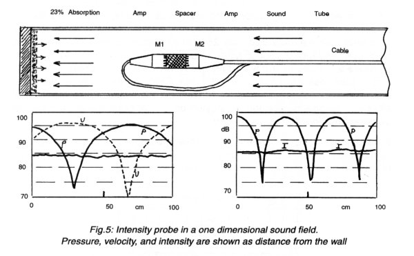
In recent years we have got instruments which can measure intensity direct. As shown in Fig.5 the instrument multiply the product of sound pressure and particle velocity using two microphones. The pressure p is taken from the sum of the two microphones and the velocity of the particles v is calculated from the difference. In this way any influence from the reflections or from outside noise are eliminated. From this one might think that it is not necessary to have an anechoic room at all when using an intensity analyser. But that is wrong as the class 1 intensity analyser according to IEC standard is required only to handle ± 12dB pressure variation and naturally also 24dB velocity variation. This is a very small dynamic range which often is not sufficient in a normal acoustic hard room. Therefore anechoic test rooms are still necessary. But we do not have to build them as perfect and expensive as it is done when we only measure sound pressure.
The conclusion is that we shall use different anechoic chambers. Besides free field and semi-anechoic we shall have small rooms and large rooms. We need test rooms with good quality for lower frequencies and others for higher sound frequencies. We have to decide if we mainly will use pressure or intensity measurements. Lastly we have to look at the economy.
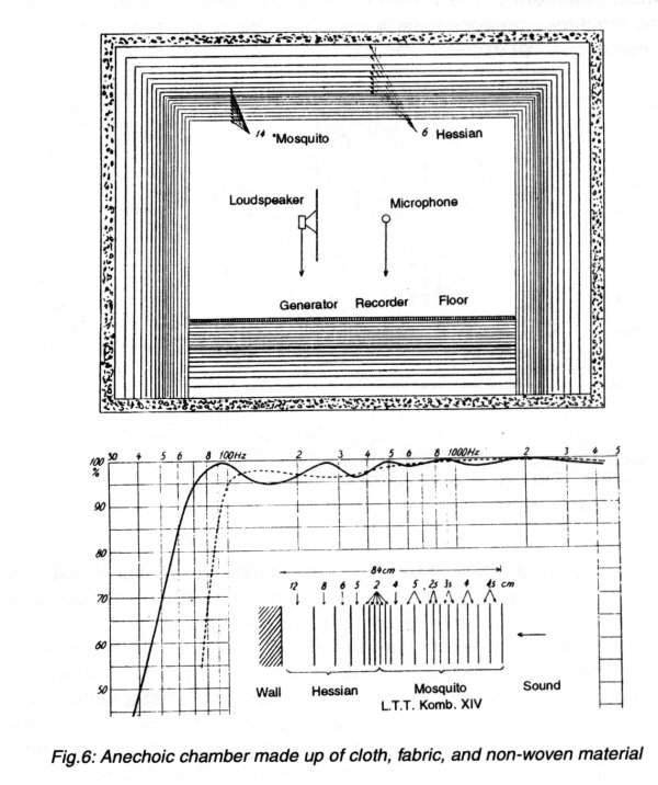
A) Several layers of tissue (cloth, woven material, fabric) with increasing flow resistance from inner to outer, see Fig.6. The inner layer could be a mosquito net and the following ones should be some heavier woven material. The other layer can be made of non-woven material with increasing thickness and flow resistance. Just inside the fixed solid wall there should be an air space of minimum 10 cm for low frequency absorption. It is very difficult to calculate the optimum configuration as there is so many parameters to choose among such as different spacing between layers and different dynamic flow resistance. But by measuring in a SWT hundreds of combinations and different materials can fast be tested and good results can be obtained. A positive thing is that it is possible to avoid mineral fibres which many people do not like. The negative side is that it is nearly impossible to find useable fire resistant material. The fire risk can, however, be reduced by chemical treatment of the woven material. The chemicals normally smells and by fire it may produce toxic gasses. A higher price is also a hinderness for these acoustical excellent rooms.
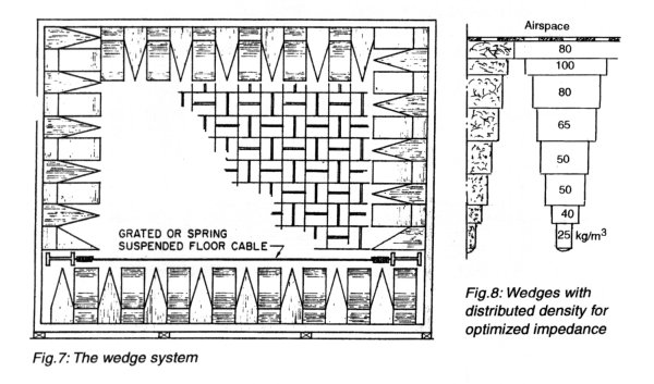
b) The wedge system is the most common principle used for anechoic chambers. It is from an acoustical point of view an extremely good solution and easy to make. Fig.7 shows the principle. The wedges are cut out of a thick mat of mineral wool which makes the whole production economic with no waste. At higher frequencies the wedges have the drawback, that when the sound comes nearly parallel to the wall, it is possible to get a reflex from the large flat surface of the wedge. This may be avoided by having the density of the glass wool less heavy in the tip of the wedge than in the bottom. A distributed density is shown in Fig.8. This changing density would also give a better impedance matching. No one have until now made wedges with distributed density. The orientation of the fibres is also very important.
Another disadvantage with the wedge solution is that the wedges often are placed direct or close to the solid wall, where the particle velocity is minimal. The consequence is a very reduced absorption. The result is that most of the mineral wool is wasted as the air cannot go through the solid wall. The mineral wool should be placed where the velocity of the particles is considerable, and it should have the correct impedance around 400 Rayl.
L. Cremer
In 1952 professor L. Cremer at Berlin Technical university suggested to build a room as shown in Fig.9.
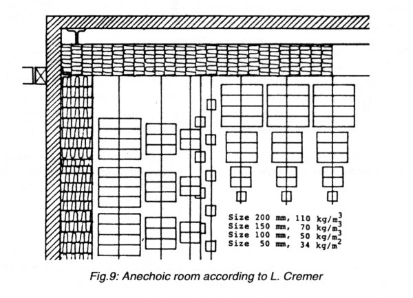
The absorbing wall consists of a solid glass fibre layer close to the solid room wall, and hereafter cubes of glass wool of different density. The cubes should not be mounted too regularly, but rather at random. Professor Cremer called this construction an "acoustic jungle". The construction works beautifully up to some MHz. So the Cremer principle should be uses when accurate high frequency measurement is required. The author has contributed to several of these rooms etc. Test rooms at B. & K., Nćrum, Lund and Gothenburg Universities in Sweden, and in Rio de Janeiro, Brazil. All rooms work perfectly. A thumb rule says that a serious absorption only can be obtained if the absorbing construction is at least l /8 or better l/4 thick. So by 50 Hz where the wave length is l = 6,8m the thickness of the wall has to be 80 cm to give some absorption and 1,5 m thick to be good. If this large volume has to be filled with mineral wool the price for the last octave at lower frequency will be extremely high. But as mentioned earlier the mineral wool close to a solid wall is of little use as the velocity of the particles with low frequencies is only fractional. Consequently it can just as well be air.
Economise with Mineral Fibres
As can be seen from Fig.10 the velocity of the particles is low close to the partly reflecting wall, but maximum around l /4 from the wall. Consequently the absorbing material should be placed in some distance from the wall. 100% absorption can be obtained with a very thin layer of flow resistant material (R), placed l /4 from the wall. But for frequency one octave higher the absorption will be very low, as l /2 will have moved to R. Here the velocity is low and consequently also the absorption. If we want several octaves to be absorbed we use a flow resistor with a certain thickness.
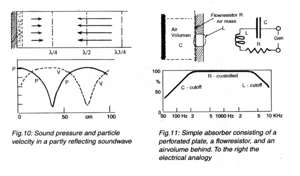
Fig.11 shows a simple absorber built of a perforated plate, a flow resistor, and an airfilled volume between plate and to the right the electrical analogy. The inductance L corresponds to the moving mass of air in and around the hole in the plate. The capacitor C corresponds to the air volume behind each hole. The resistor R is the flow resistance at the hole. From the electrical analogy can be seen that if we want maximum electrical energy wasted in R the generator impedance should also be R and the impedance of both C and L should be as small as possible. From this can be deduced: low frequency will be hampered by C, so therefore low frequency absorption can only be obtained by having a large air volume behind the perforated plate. The high frequency will be stopped by L. Therefore the perforated plate have to be thin and the perforation should be many small holes placed close together. The flow resistor should have the same impedance as the acoustic impedance of air. In his case you can get an absorption as shown in Fig.11. A large frequency range where the absorption is nearly 100%. Both at the low and high end we will see a drop in absorption due to high impedance in L to C. We can see that a lot of mineral fibres with low frequency absorption can be saved just by having the right flow resistance in a relative thin layer (5-10 cm) and a large volume behind the flow resistor. In this way a considerable absorption can be obtained down to 30-50 Hz with a small amount of fibres, but the air volume must be large 1-1,5 m.
An acceptable Solution
By combining all our knowledge and experience about anechoic chambers we can make the following suggestions and describe a modular system, which not only is modular in linear dimensions (40 or 60 cm), but also in a way so that clients can start building only a part of the construction and later on get further units for a more complete system.
We can make test rooms specially for cars, buses or large machinery. In these cases the lower frequency is very important, but the higher frequencies (over 1kHz) have less importance. The construction is very simple and can be built for a reasonable price. To protect the flow resistor an open metal net can be installed. The net allows all frequencies up to 4 KHz to pass.
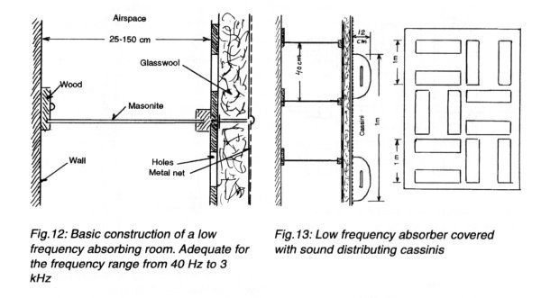
Besides the lack of absorption of higher frequencies the large flat surfaces are also a drawback. It can be considerably better by installing some curved metal net containing a thin layer of 2-3 cm of mineral fibres with a very low density, see Fig.13. This sound distributors should not cover the whole surface, but leave around 1/2 of the total surface. Rooms of this simple construction are normally for measuring big objects and will be semi-anechoic with a hard floor. By using an intensity analyser instead of a SLM a very high precision can be obtained.
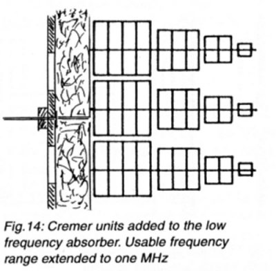
Smaller rooms for testing objects are household equipment, motor cycles, gears, and other mechanical products should also be semi-anechoic rooms made as indicated in Fig.12 and Fig.13. but do not make them too small. If the object generate frequency of any importance over 1,5 KHz Cremer units should be added, see Fig.14 and then there is no limits for higher frequencies.
Movable Floor Units and Doors
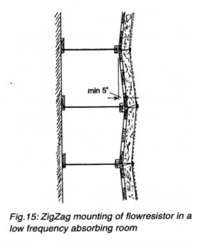
Another way to avoid the large flat surfaces in walls and ceilings is to mount the plates which carry the flow resistor in a zigzag way, see Fig.15. Careful investigations of constructions of radio studios have shown that an angle of ±5° is absolutely sufficient.
Objects like sound level meters, loud speakers, hearing aids and rooms for psycho-acoustic work should all be free-field rooms with absorbing floors. As a conventional floor net is both expensive and impractical, it is suggested that the floor is built up as separate units, Fig.15. The units should be light, so it is easy to stack them and by this method make a corridor for installing the equipment. This is a very flexible system, fast and accurate to work with.
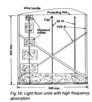
The absorbing floor units are very light (3,5 kg/for 40x40 cm) see Fig.16 so they can be lifted with hands. The units are placed on the floor during measurements. During preparation for the measurements some units are lifted up and placed on top of the neighbour unit. In this way the testroom is very flexible as it can be used both as a free field and a semi-anechoic chamber. The only disadvantage is that the floor does not have the low frequency absorber.
The door to the room is like the floor units a very simple and light construction made of 10mm Al-tubes. The door can also easily be lifted out and put in position as it only weights a few kilograms. To make hinges and handles for a door 0.5-1.2 m thick is a difficult and costly procedure. The result is always a clumsy solution which takes time to operate. The disadvantage with a light door is that the insulation from outside noise is low. But as mentioned earlier this is normally only required for psycho-acoustic measurements. Industrial noise is always measured at a higher level, where a limited sound insulation can be tolerated. It may be practical to roll the door on gliding tracks both out and then sideways.
Testing Anechoic Chambers
The classic method to test an anechoic chamber is to use a point sound source and apply the distance law: 6dB drop for doubling the distance. By using a log scale for the distance the pressure drop should be a straight line, see Fi.g17. It is very difficult to make a monopole sound source. A loud- speaker in a baffle or even in a cabinet will always radiate some sound from the reverse side. A solution is to install a mini loudspeaker in a solid sphere (Fig.17) filled with absorbing material. Using pure tones for testing is unrealistic as practical all the noise sources which should be tested in the room are broad band noise. Therefore if you from an inverse distance curve will estimate the accuracy the test signal should be a narrow band.
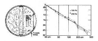
Fig. 17:Monopole source for checking the inverse square law in anechoic chambers. Right some results.
Standing Wave Tube
Another solution for testing the quality of an anechoic wall is to evaluate the absorbers on the wall in a Standing Wave Tube (SWT). We have made and used two tubes with different cross-section. One is a quadrangle 40x40 cm and the other is circular with D=10 cm and 3 cm, Fig.18. With the shown set up it is possible to measure from 50 Hz to 6500 Hz. In another paper we will describe the SWT used here in more details.
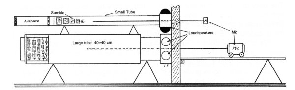
Fig. 18: Standing Wave Tube (STW) for testing absorbers intended for anechoic rooms in frequency range 50 Hz to 6000 Hz. Divided over 3 tubes 40 x 40 cm, D=10 cm and D=3,2 cm. The square section tube has sand filled wall to eliminate vibrations in the walls.
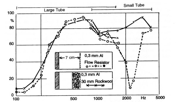
Fig.19: Example of "absorption drop" at half wavelength l/2 when
the resistor is very thin.
With a thicker resistor the absorption curve is
much flatter
The SWT gives a high accuracy of the absorption of the particular sample. The problem is to make a sample which is representative. The psychological disadvantage is: 1) it is the lowest absorption coefficient which exists. 2) With a thin flow resistor just l/2 from the background a drop in absorption occurs. This effect is shown in Fig.19 for a very thin plate and an interspace of 7 cm. With a somewhat thicker resistor this phenomenon is gone. Fig.20 illustrates how the absorption increases with the angle of incident. The solid curves are valid for most absorbents consisting of textiles or mineral fibres. The dot and dash curves indicate when the soft material are covered with some perforated plates which introduce an imaginary impedance.
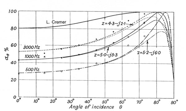
Fig. 20: The absorption of porous material with different angle of incidence
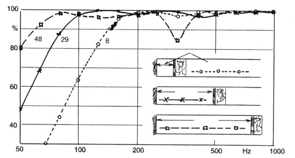
Fig. 21: Absorption for the same flow resistor mounted with different airspace.
The origin of these theoretical curve dates back to P. M. Morse, R. Bolt and L. Beranek in the years 1938-39. The points are experimental verification of the theory. It is shown that the absorption always is found grater than the theory predicts. We have not been able to verify the theory beyond 75° incidence. The curve marked Cremer is the theoretical prediction for absorbers made from glass wool cubes. It appears that if the absorption measured in a SWT is 98% the effective absorption already with 20° incidence is close to total absorption. We will later write a paper about this interesting problem. We have together with Florence University under the MONICA project made some measurements converting SWT results to effective absorption in rooms.
Practical Configurations
Fig.21 illustrates how the absorption changes with the distance between the solid wall and the flow resistor. It is seen that low frequency absorption only can be obtained by using a large airspace or thickness of the absorber. This construction is often sufficient for large projects like buses, cars, large tool machinery, etc. as it is economical for large rooms. A room of this type will work excellent together with some layers of Cremer cubes.
On Fig.22 is seen how the low frequency room shown in Fig.21 can be transferred into a room with a perfect high frequency absorption. The drop at 500 Hz and 1500 Hz is due to perpendicular incidence. It is averaged out for random incidence for frequencies over 300 Hz. As shown here the Cremer configuration is excellent for middle and higher frequencies, and the lower frequencies is be taken care of with a resistor type absorber.
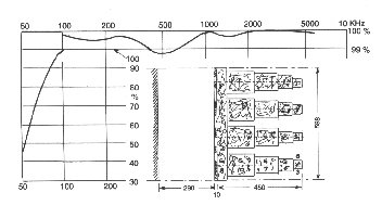
Fig.22: A good construction for a wall for an anechoic chamber with Cremer absorbers.

® Web masters Mario
& Paolo Mattia - updated on April 2003, Web Master
On line from 1995 November 10