Brüel Acoustics
Elements for Anechoic Chambers
By Dr. techn. Per V. Brüel.
The elements are intended for construction of different anechoic chambers. With reference to Brüel Acoustic Technical Review 96-02 we can divide anechoic chambers in the following groups:
All the above-mentioned rooms are intended to be used for sound pressure measurements which require more than 99% absorption of the walls and ceiling.
Such a high absorption is difficult to get at lower frequencies. When testing large objects like cars it is an advantage to use techniques where measurements can be made in the near field. Many people are of the opinion that using the intensity principle makes it possible to omit the anechoic chamber.
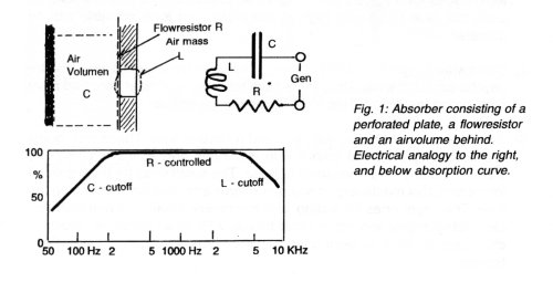
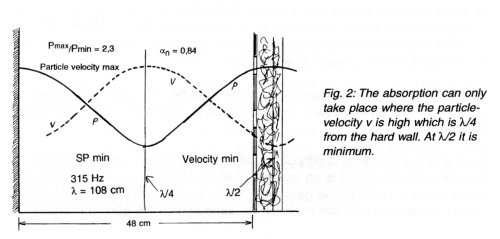
That is a truth with modifications especially concerning lower frequencies where the wavelength is large. The particle-velocity is determined from the pressure difference between the two microphones. With a longer wave- length this difference is extremely small and consequently the requirement to the internal S/N in the electronics is high. If the sound field is reverberant further increase in S/N will be required. Measuring on large tool machinery, cars, busses, power transformers and other larger equipment should be tested using intensity. But in this case high absorption at low frequency is necessary. Brüel Acoustics (BA) have made an absorption element based on the flow resistor theory, which is used in AcoustiCone and AcoustiCassini (fig. 1). For low frequency absorption a large airspace is necessary. There can be a decrease in absorption at places where the distance from the resistor layer is V2 see fig. 2. These drop in absorption occur only for sound coming perpendicular to the wall. For all other angle of incidence this dip is smeared out.
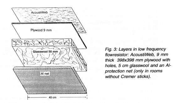
A low frequency semi-anechoic room is built of BA flow resistor elements and with airspace ranging from 30 to 120 cm. The 5 cm glasswool is made of special, curled fibres and covered with an acoustic inactive protection grid (fig. 3). The flowresistance depends on the thickness of the Web, the dimensions of the holes in the wooden plate and finally the density and direction of the fibres in the wool. Before manufacturing a batch of elements both Web and glasswool are controlled in a large SWT. Particularly in the glasswool large differences are found from batch to batch.
High absorption at low frequencies is normally obtained by using a thick layer of mineral wool. But here the low frequency absorption is based on a 6 cm thick flowresistor where the lower cut-off frequency is determined by the depth of the airspace, fig. 4.
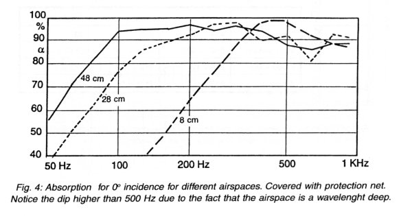
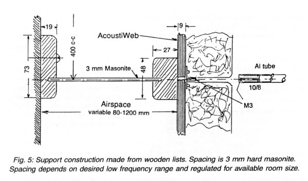
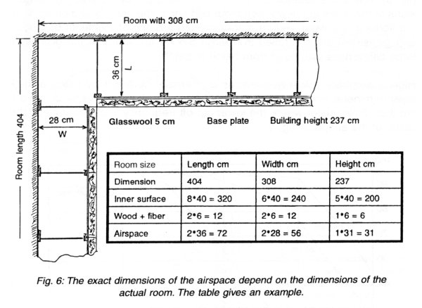
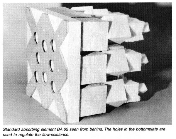
Fig. 3 shows the basic flowresistor made in the module size 40 x 40 cm (type 62 BA). The protection grid shown on the figure is not a part of the flowresistor. The protection grid is only used for rooms where the low frequency absorption is the most important and intensity measurements are made.
The support and the distance to the fixed wall are made as seen on fig. 5. The support is made locally in order to save cost. By varying the airspace the modular flowresistor of 40 x 40 cm can fit into any size of room. The adjustment is done by letting the "odd" measures be taken up by variation in air- space, fig. 6.
A room covered with this absorber will be excellent for work with intensity instrumentation. Another advantage is that if a workshop is treated with this low frequency absorber the noise level will be reduced dramatically as there is still an appreciable absorption also for higher frequency.
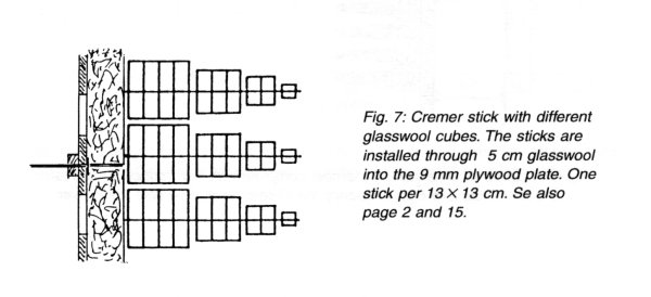
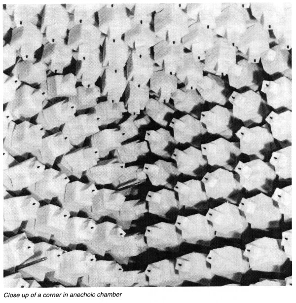
For middle and higher frequencies we use the Cremer principle with cubes of glasswool. It is an old well-known construction which has been used for more than 30 years in many countries. The advantages over the wedge system are that they are superior and more flexible at higher frequencies. Many laboratories work up to 0.5 and 1 MHz in Cremer rooms. The reason for this excellent result is that the glasswool cubes are of different density with the lightest material in the tip and the more dense and larger cubes are at the back. The other reason is that the absorption can be optimised by changing the dimension of the cubes. Up to now most of the cubes in Cremer rooms support the glasswool in steel wires which require a complicated tube system for fixing the wires.
Brüel Acoustics have developed a system where the cubes are supported by a thin Al-stick mounted on the base unit, see fig 7.
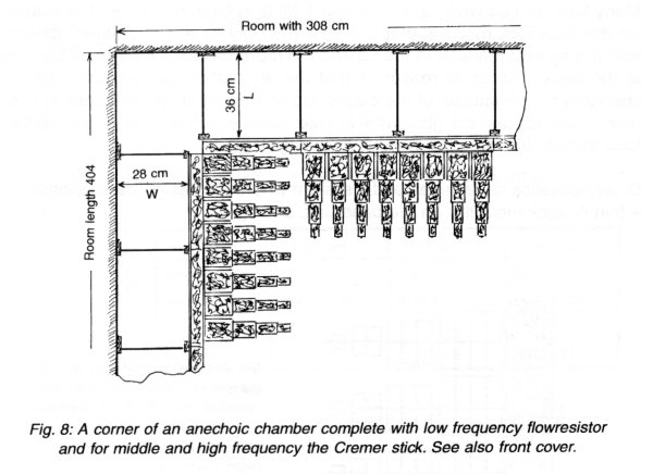
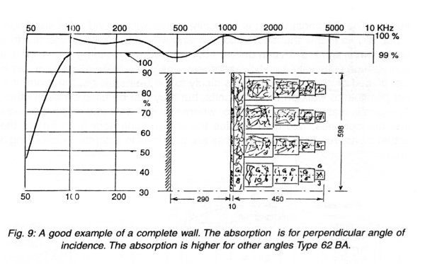
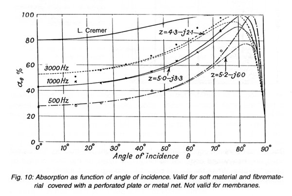
Building an anechoic wall for the whole frequency range is just to add sticks with glasswool cubes to the room see fig. 6. The metal grid must be removed. The aluminium stick is just pressed through both the 5 cm glasswool and the predrilled holes in the plywood plate as seen in fig. 8, see also front cover. There are four different cubes each with a certain size and density. The size and density is carefully controlled by BA. The cubes sit on the stick only by friction. At the end all four cubes are locked with a little rubber cap for protection. The cubes should be "turned" slightly, it increases the absorption. It has been an immense work to find a good combination with all the possible variables. More than 500 combinations have been tried and carefully evaluated. All mechanical dimensions are made with negative tolerances so it is easy to handle the mounting. Just work with a multiple of 40 cm exact. On fig. 9 is shown the absorption for 0' for a good construction. The absorption shown in this paper is all made in different sizes standing wave tubes (SWT), where very exact measurements can be made. Unfortunately perpendicular incidence (0' incidence) gives the lowest value an absorber can have. Fortunately any other incidence give higher absorption, Fig. 10.
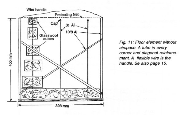
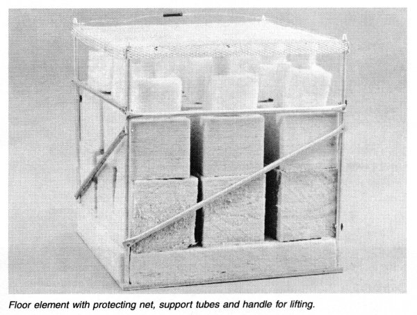
Floor: The BA construction is basically rooms with sound reflecting floors (open air) as that is the most used now and will be so in the future. If a free field room is wanted BA can deliver floor units as shown in fig. 11 which is a light Al-tube cube with the stick absorbers. The unit covers 40 x 40 cm and is just placed on the hard floor. It fits nicely to the free space in the room. It is not possible to walk on the floor units, but they can be piled on each other. The idea is that you make a corridor where you can walk and prepare objects and microphones, and then replace the few missing floor units before the actual measurements. The floor units are delivered in a cardbox containing 3 units.
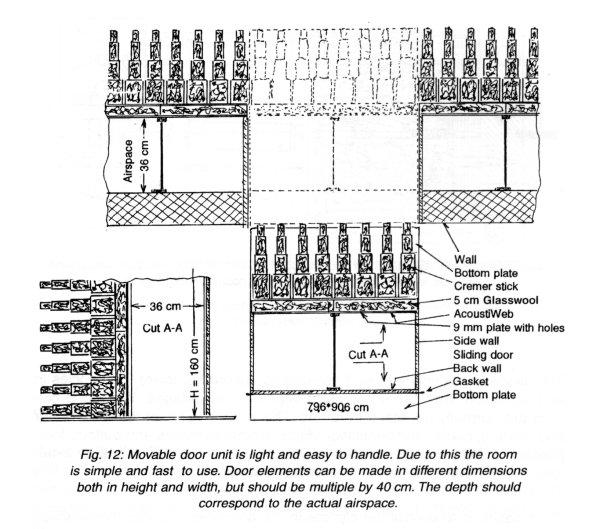
Door: The doors are equally simple. It is a very light construction. It does not need any heavy and complicated hinges. It slides on the floor guided by some tiny lists. When the door is closed a rubber gasket tightens the slit between wall and door, fig. 12.
The removable floor and the doors are very simple and economical constructions compared to what have been seen in earlier anechoic chambers. But it is the most practical and trouble-free solution you can get. It has been possible because BA has made an extremely light weight construction.
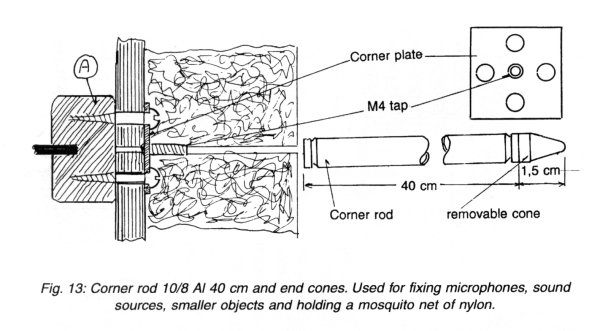
Corner Rod: The 9 mm wooden base plate is the mechanical support for the absorbing material and glasswool cubes. These plywood plates are fixed to the list A in every corner with a metal plate and 4 screws, fig. 13. In the middle of the metalplate is a tap with M4 thread. It is therefore possible to onscrew a 40 cm long Al-tube to which microphones, smaller objects, sound sources and wires may be fixed. It is recommended to order 20-30 corner rods for each room where Cremer sticks are used. A small Al-cone is screwed at the end of every single rod. It should be on when the rod is not in use for supporting purposes. Some people want to have the whole room screened inside with an open mosquito net. This net can be fastened on the rod with the AI-cones. In that case you need a rod for every corner.
In practice the complete absorbing unit is delivered as a finished cube with the measure 398x398x400 mm ready to mount on the supporting construction. The absorption for sound impending perpendicular to the wall is shown in fig. 9.
The airspace not only makes it possible to absorb the lower frequencies in an economical way, but it has other important advantages. Walls and ceilings are normally not plane in rooms. The surface is full of tubes for water and heating, cable- and ventilation ducts, electrical cables and outlets, foot- panels etc. All these do not have to be removed, it can just be hidden in the airspace. It makes the whole interior practical and tidy.
If the desire is to control the climate in the anechoic chamber the airspace which surrounds the whole room, can be heated or cooled by ventilated air in and out of the airspace. It is possible through openings in the airspace to control the airflow within wide limits. It is recommended to keep a slight over- pressure in the test room or a little under pressure in the airspace. In this way small loose particles from dust and glasswool are sucked up and deposited in a filter. The airspace is an essential part of the BA patent for anechoic rooms.
< img src="tr9602i21.jpg" width="600" height="321" alt="" border="0">
Fig.14: Absorption as function of frequency for three different airspaces and the standard Cremer sticks.
Specifications:
Base units BA 62: se inside cover consisting of 9 mm plywood with holes and a 5 cm thick layer of glasswool with controlled flowresistance. Weight per unit 1,3 kg. 3 pcs. packed in a cardboard box with the necessary mounting. Thickness 65 mm. Base 40 x 40 cm. Fig. 14 shows the absorption.
The metal net shown on fig. 3 is only for mechanical protection if that is desired. It has no influence on the acoustics. The material is aluminium with very open perforation. Thickness is 2 mm. Fittings included.
Cremer sticks: Made up of 3 mm hard Al on which the glasswool cubes are mounted. At the end of the sticks are a rubber protector which also locks the cubes. Normally the sticks are delivered on a base unit (without metal net) complete with fittings ready for installing. There are 9 sticks on a 40 x 40 cm base. Weight is 3,6 kg. Absorption see fig. 9. The length of the tube stick is 40 cm. Two units are shipped in a cardbox with dimensions 41 x 41 x 82 cm for type 62 BA.
Corner rod: Al-tube 10/8 mm, length 40 cm. Threads M3 in both ends. To each rod a small Al-cone with M3 is delivered.
Advantages of Brüel Acoustics' Anechoic Chambers:
1) It is versatile as big rooms and small rooms can be build.
2) The rooms can be made for only low frequency and intensity measurements or for full frequency range.
3) The rooms are convertible from open air configuration to full free field.
4) Very effective for middle and high frequency due to the Cremer cubes where the density is optimised with low value close to the room and high density further back.
5) It is light weighted because instead of heavy packed mineral wool close to the fixed wall there is only an airspace. It also save money.
6) It is also economical because the supporting structure is so simple that it can be made on the spot.
7) The test chamber can be installed in all kinds of rooms.
8) The rooms can use the airspace for heating and cooling.
9) A patent application has been made for this unique construction of an anechoic room.
Ó Brüel Acoustics - from G.Mario Mattia, Rome, Italy, august 1998.

® Web masters Mario
& Paolo Mattia - updated on April 2003, Web Master
On line from 1995 November 10