Brüel Acoustics
Oscillator for Acoustics
Dr. techn. Per V. Brüel
Most of the time when we make acoustic measurements, we need an oscillator to feed a loudspeaker. What is the preferred specification for the oscillator? It depends, of course, on the kind of work you want to do.
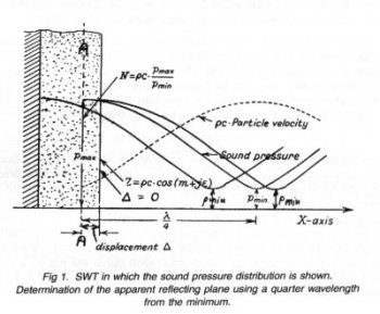
Oscillator for Standing Wave Tube (SWT):
Here we need a very pure sinusoidal signal. The even harmonics are especially problematic as they have a maximum where the fundamental frequencies have a minimum (fig. 1). When measuring low absorption, the ratio n = pmax/pmin is large and thus there is only a limited S/N ratio. Another requirement is that it must be easy to measure the distance D (see fig.) to the plane A-A where the reflection "apparently" takes place. If this plane is at the solid back wall, the damping material is too soft. If the reflection takes place at the front, the material is too hard. The optimum is somewhere in-between. This means that for every frequency, we have to find pmin and calculate the corresponding quarter wave- length l /4 to determine the "reflecting plane". All of this is much easier if only a limited number of frequencies are used. In most acoustic standards it is recommended that the so-called preferred frequencies are used. ISO standard 266 comprises several series and has recently been renewed. For acoustic work, the most commonly used system is ten frequencies per decade or practically every 1/3 octave. If we have an oscillator where these frequencies are generated by simply pressing a button, the work would be easy and only few mistakes would occur. For practical reasons the oscillator must be able to drive even a large SWT without requiring a power amplifier, so a power output of one watt into the LS impedance would be ideal.
For many measurements with a SWT, a PC is used for post-processing of the results and/or writing reports. For this purpose, the oscillator should also be able to be controlled from a PC. The oscillator should also be small, have an attractive design and not be too expensive. It is expected that quite a number of acousticians will have a complete SWT system in their offices because a SWT can be used to check so many things. See BA T. Review 97- 01.
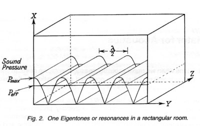
Reverberation Measurements:
are generally performed using a band of noise as excitation. The noise will energise most of the room resonances within the band (see fig. 2). The reverberation curve is the sum of the resonances as a function of time. Each resonance has its own exponential decay of amplitude like any other harmonic wave movement. If the exponential amplitude is expressed on a logarithmic scale, the decay curve becomes a straight line. When all the resonances within the noise-band are added up with their individual damping, the reverberation curve will not be a straight line. It will be steeper at the beginning and thereafter flatten out (fig. 3).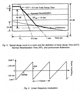
If you repeat a reverberation measurement process, you will find that the reverberation curves are all different. What happens is that every single resonance is energised differently each time, since the noise-band consists of uncorrelated sound pressure amplitudes and also uncorrelated frequencies. The consequence is that you get different results every time you start a new reverberation measurement. All the difficulties occur only because an uncontrolled noise signal is used. We therefore want a signal which can be repeated accurately in amplitude, frequencies, and phases. Furthermore we require a signal which would energise each resonance with the same amplitude. This can be achieved by making a linear frequency modulation (fig. 4). When measuring reverberation in large rooms, it is convenient to start and stop the oscillator at some distance by remote control, e.g. in sports-halls, swimming pools, air terminals and concert halls.
Measuring Absorption in a Reverberation Room:
According to ISO 11654, the reverberation room must have a minimum volume of 200 m3 and exhibit sound diffusion. Loudspeakers are normally fixed in corners for energising the maximum number of resonances. The microphones are often moved during the measurements (fig. 5). Both the sound source and microphone are controlled by a PC for automatic measurements. The oscillator should therefore also be controlled by a PC. The measurements are normally only carried out at preferred frequencies so it would be an advantage if these frequencies can be produced in a convenient way. If the signal can be made repeatable, a lot of time can be saved when series of absorption curves, like the ones shown in fig. 6, are made.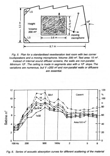
Sound Insulation of Walls:
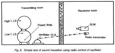
Many international and national standards exist describing how to measure wall insulation. They all use the principle of generating a sound signal on one side of the wall and measuring on the other side (see fig. 7). In many cases there is a cable connection between the transmitter and receiver room in order to control a generator. But installing a cable through the wall is always a problem and thus a radio or other form of remote link for synchronisation is a must. The radio link must only be used to signal start, stop, and frequency changes. Systems exist in which the signal itself is transferred by a common radio link. But this solution is both expensive and gives rise to failures due to the low S/N ratio. The only sensible solution is to have the oscillator, amplifier, and loudspeakers in the transmitting room, (fig. 7 and fig. 8).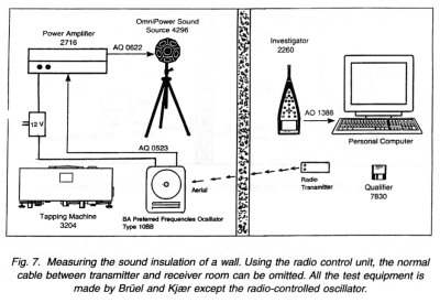
Sound Insulation of Heavy Walls:
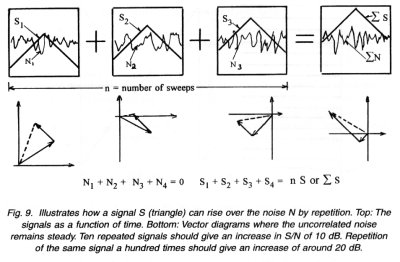
It is always very difficult to measure walls with high sound insulation for two reasons. The mechanical vibration (flanking effects) is often the major path for the sound energy. If this is the case, only sound intensity measurements can help to determine the insulation of the wall. But high sound insulation of the wall itself can be difficult to measure because the signal on the receiver side is so weak. The power in the transmitter-room must then be increased. This is expensive and requires heavy equipment. For normal walls, 10 W may be sufficient. If a 20 dB higher signal level is necessary, 1000 W is needed. This will normally be out of question.A good solution would be to trade power with time and use a generator with a repeatable signal and correlate multiple signals on the receiver side. 10 signals can lift the signal 10 dB out of the noise. 100 signals can result in up to 20 dB lift in S/N ratio, (fig. 9).
The repeatable signal can be used for many other applications, for example for underwater acoustics where the S/N ratio is often close to the limit for measurement. Here you can also lift the signal out of the noise using the correlation technique. Remote controlled start and stop facilities are essential in underwater acoustics since the distances involved are sometimes several kilometres.
Linear Frequency Modulation:
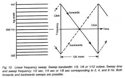
The oscillator has an unusual frequency modulation, with time linear sweep over a log frequency scale. Let us take an example (see fig. 10). Preferred frequency: 501.2 Hz. Frequency modulation: 1/3 of an octave, i.e. ±1/6 octave. Sweep Frequency: 4 Hz. Of course, it is not possible to have a periodic signal with a duration of 250 msec giving unlimited numbers of distinct frequencies. A Fourier analysis shows that there must be 4 Hz between each produced frequency. This is indicated on the figure. So a compromise must be made either by modulating slowly and getting many distinct frequencies or by modulating fast and getting a longer distance between each frequency. The sweepback is very fast and will naturally give a short click in the system. But the frequencies here will be higher than any frequency in the 1/3 octave. The click contains only a very small amount of energy and will normally be filtered out. It may, however, be mentioned that it can be used as trigger mark for the start of the signal.The sweep can be directed either from the low end of the frequency band towards the high end or from the high end to the low end. There may be a difference in the Early Decay Time (EDT) when the reverberation is short. For normal reverberation time which is determined from the decay curve from -5 to -35 dB, the difference between forward and backward sweeps is negligible.
Slow Frequency Sweep:
When controlled from a PC, the oscillator can operate through any frequency range at a slow speed. In this case it is possible to record even steep, undamped resonances. In both the plastic and paint industries there is an interest for measuring the elasticity and damping decrement of small sampling strips. The instrument is called a Complex Modulus apparatus. The slow and precise moving frequency oscillator is excel- lent for this type of work.By measuring the frequency response from one point to another, it is possible to find flutter-echoes in rooms and concert halls. When the frequency range and the position of the flutter echoes are found, it is rather simple to eliminate the flutter either with some high frequency absorption on one of the reflecting walls or by sound diffusing devices.
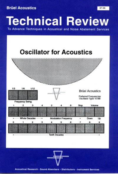
Brüel Acoustics Preferred Frequencies Oscillator
Brüel Acoustics has developed a small oscillator for acoustic measurements.
This instrument is called Preferred Frequencies Oscillator Type 10 BB.
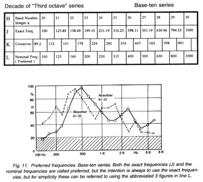
Frequency Range: 10 Hz to 80 KHz. 40 preferred frequencies in fixed steps of 1/3 octaves These frequencies are base-10 series where the frequency is determined by f=10n/10. n is an integer, either positive or negative. In this oscillator, n has a value between 10 and 49. We also call n the band no. (see the illustration fig. 11). The crossover between bands is also shown.
Distortion:
25 Hz: 0.13%
>100 Hz: 0.15%
1 to 10 KHz: <0.15%
40 KHz: 0.4%
Output power into 4W :
Minimum 1 W over 100 Hz.
Each preferred frequency can be frequency modulated with a bandwidth of 1/3, 1/6, or 1/12 octave.
Modulation Frequency: 2-4 Hz and 8 Hz.
Modulation: linear from low to high or from high to low.
Sweep back in less than 10-4 sec and always cutting in and cutting out at zero point. In this way the signals can be exactly repeatable.
Control: Manual with built-in keyboard.
Computer through R 256.
Radio: Through built-in radio receiver and controlled by a hand- held transmitter with four control buttons.
Range: 300 m in open air. Operates through 36 cm brick wall for short distances.
CE-Marking: Comply with EU requirements for radio emission.
Power Supply: 10-20 V DC with positive pole in center.
Preferred Frequency
Survey of preferred frequencies, bandwidth, and crossover frequencies.
© Brüel Acoustics - from Dr. Per V. Brüel & Dr. G. Mario Mattia, Rome, Italy, august 1998.

® Web masters Mario
& Paolo Mattia - updated on April 2003, Web Master
On line from 1995 November 10